Analysis Flow
Analysis Flow and Input/Output File
Analysis Flow
The input and output file of the structural analysis code FrontISTR is shown in Figure 3.1.1.
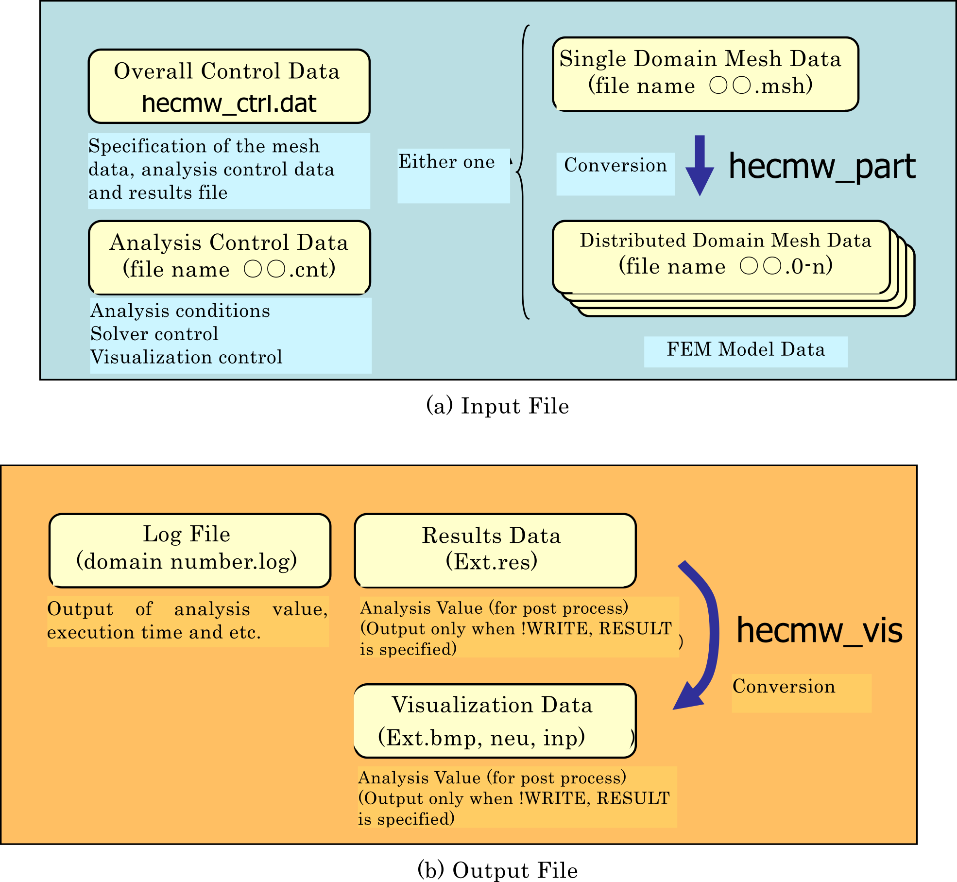
Figure 3.1.1:FronntISTR Input/Output File
FrontISTR requires three files, such as the overall control data, mesh data and analysis control data as input files.
When analyzing the overall model with a single CPU, the single domain mesh file is used. When performing parallel execution with multiple CPUs, the distributed domain mesh data as a result of performing domain partitioning of the single domain mesh data in advance by the hecmw_part program which is the partitioner of HEC-MW in used.
The overall control data, analysis control data and single domain mesh data are text data. The user can create and edit using the proper editor, according to the description in this manual. The user can also create files using neu2fstr which converts a neutral file (*.neu) supported by Femap which is a pre-post processor sold commercially as an attachment tool for FrontISTR, into FrontISTR input data.
Executing FrontISTR will output the log data file, results data file and visualization data. The existence and content of these outputs, depends on the description and analysis content in the analysis control file.
After FrontISTR is executed, the visualization data can also be created from the created results file by the hecmw_vis program which is a tool included in HEC-MW.
Overall Control Data
This file specifies the input file and results output file of the mesh data and analysis control data.
The details of the overall control data are described in Chapter 5.
(Example)
!MESH, NAME=fstrMSH,TYPE=HECMW-DIST
Definition of header of the distributed mesh data file (mandatory in the domain distribution model) : Foo_P16
!MESH, NAME=fstrMSH,TYPE=HECMW-ENTIRE
Definition of mesh data file name (mandatory in the single domain model) : Foo.msh
!CONTROL,NAME=fstrCNT
Definition of analysis control data file name (mandatory) : Foo.cnt
!RESULT,NAME=fstrRES,IO=OUT
Definition of analysis results data file name (arbitary) : Foo.res
!RESULT,NAME=vis_out,IO=OUT
Definition of visualization file name (arbitary) : Foo.vis
Mesh Data
This file defines the finite element mesh, and defines the material data and section data. This file also defines the group data used in analysis control data.
The details of the mesh data are described in Chapter 6
(Example)
!HEADER                             ----- Setting of mesh title
 TEST MODEL A361
!NODE                               ----- Definition of node coordinates
 0.0,0.0,0.0
!ELEMENT,TYPE=361                   ----- Definition of element connectivity
 1001,1,2,3,4,5,6,7,8
!SECTION,TYPE=SOLID,EGRP=ALL,MATERIAL=M1  ----- Definition of section data
!MATERIAL,NAME=M1,ITEM=1            ----- Definition of material data
!ITEM=1,SUBITEM=2
 4000.,     0.3
!NGROUP,NGRP=FIX,GENERATE           ----- Definition of node group
 1001,1201,50
!EGROUP,EGRP=TOP,GENERATE           ----- Definition of element group
 1001,1201,1
!END
Analysis Control Data
This file defines analysis control data, such as the type of analysis, displacement boudary conditions, concentrated load and etc. Control of solver and the control data of the visualizer are also included in the analysis control data.
The details of the analysis control data described in Chapter 7
(EXAMPLE)
!! Analysis Type
!SOLUTION,TYPE=STATIC            ----- Specification of analysis type
!! Analysis control data
!BOUNDARY                        ----- Definition of displacement boundary conditions
 FIX,1,3,0.0
!CLOAD                           ----- Definition of concentrated load conditions
 CL1,1,-1.0
!DLOAD                           ----- Definition of distributed load conditions
 ALL,BX,1.0
!REFTEMP                         ----- Definition of reference temperature
 20.0
!TEMPERATURE                     ----- Definition of heat load (temperature) coditions
 ALL,100.0
!! Solver Control Data
!SOLVER,METHOD=CG,PRECOND=1,TIMELOG=YES,ITERLOG=YES ----- Control of Solver
 10000,2
 1.0e-8,1.0,0.0
!! Post Control Data
!WRITE,RESULT                    ----- Analysis results data output
!WRITE,VISUAL                    ----- Visualizer control
!! Visualizer
!visual                          ----- Hereinafter, the control data of the visualizer
!surface_num=1
!surface_style=1
!END
Log File
When the execution is completed, the log file (Ext.log) will be output.
The contents of the log files shown in the following will be output.
- Displacement, strain, Max/Min values of stress component
- Eigenvalues
- Engenvector values
Analysis Results File
The analysis results file (Ext.res) for visualization will also be output by specifying the output.
*fstrresult 2.0
*comment
<comment>
*global
<the number of global parameters>
<dof of global parameter> ...
<label of global parameter>
...
<value of global parameter>
...
*data
<the number of nodes> <the number of elements>
<the number of node variables> <the number of element variables>
<dof of node variable> ...
<label of node variable>
...
<value of node variable>
...
<dof of element variable> ...
<label of element variable>
...
<value of element variable>
...
Execution Procedure
1. Preparation of FrontISTR
Save the main body of FrontISTR (Linux ver.: fistr1, Windows ver. : fistr1.exe) in the path directory, or the current direct directory at the time of execution.
2. Preparation of Input Files
Prepare three types of input files hecmw_ctrl.dat, analysis control and (single or distributed domain) mesh data, and enter the file name (pathname) of the analysis control data and mesh data in hecmw_ctrl.dat. If necessary, also specify the analysis results data file and the visualization data file.
3. Execution of Single Domain Analysis
Start the Linux terminal or the command prompt of Windows, move the current directory to the directory with the input file, and execute the analysis as follows (however, > refers to the prompt).
Example : In the case of Linux
> ./fistr1
Example : In the case of Windows
> fistr1
4. Parallel Execution on Linux
In the Linux ver., the MPI must be installed in advance, and compiled for parallel execution. For details of the compiling method, refer to the Installation Manual. The execution depends on the settings of the execution environment of MPI. An example of execution int four domains is shows in the following.
> mpirun -np 4 ./fistr1
5. Parallel Execution on Windows
In the Windows ver., it is necessary to download the library of MPICH2 from the following URL and install. For the method of parallel execution, refer to MPICH2 Manual.
6. Execution of Parallel Domain Contact Analysis (Note for users from Ver.3.x)
Until Ver.3.x, only when performing contact analysis, users had to always specify single domain mesh file as input mesh no matter if it is serial or parallel analysis. Starting from Ver.5.x, this exception was removed; i.e. users have to specify single domain mesh file as input mesh when performing serial contact analysis, distributed domain mesh file as input mesh when performing parallel contact analysis, just like other analysis types.