Non-Linear Static Analysis (Hyperelasticity, Part 1)
Non-Linear Static Analysis (Hyperelasticity, Part 1)
This analysis uses the data of tutorial/03_hyperelastic_cylinder.
Analysis target
The analysis target is a 1/8th model of a round bar. The geometry is shown in Figure 4.3.1 and the mesh data is shown in Figure 4.3.2.
| Item | Description | Remarks | Reference |
|---|---|---|---|
| Type of analysis | Non-linear static analysis (hyperelasticity) | !SOLUTION,TYPE=NLSTATIC | |
| Number of nodes | 629 | ||
| Number of elements | 432 | ||
| Element type | Eight node hexahedral element | !ELEMENT,TYPE=361 | |
| Material name | MAT1 | !MATERIAL,NAME=MAT1 | |
| Material property | ELASTIC | !ELASTIC | |
| Boundary condition | Restraint, Forced displacement | ||
| Matrix solver | CG/SSOR | !SOLVER,METHOD=CG,PRECOND=1 |
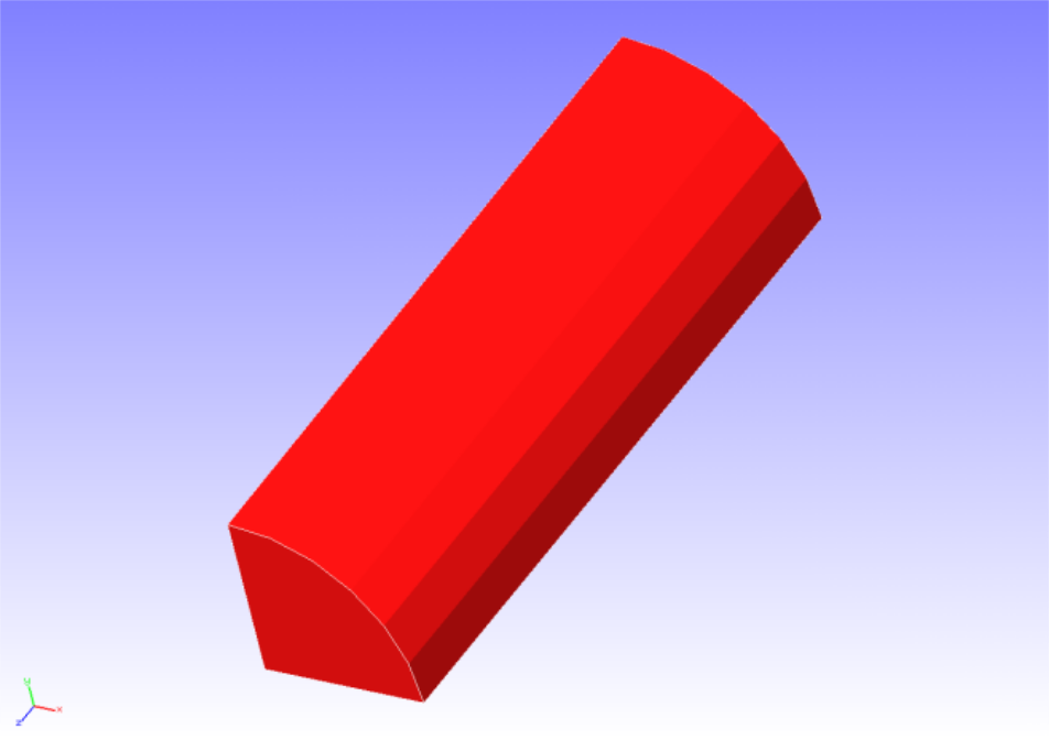
Fig. 4.3.1 : Shape of the round bar (1/8 model)
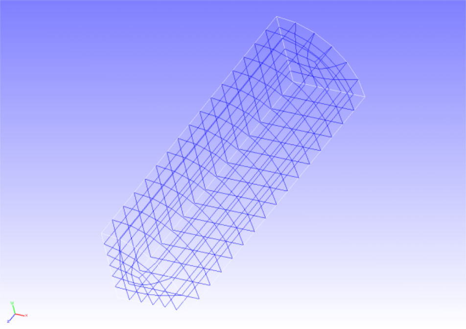
Fig. 4.3.2: Shape of the round bar (1/8 model)
Analysis content
In this stress analysis, an axial tensile displacement is given to a round bar. The Mooney–Rivlin model was used in the material constitutive equation of hyperelasticity. The analysis control data are presented below.
Analysis control data cylinder.cnt
#  Control File for FISTR
## Analysis Control
!VERSION
 3
!SOLUTION, TYPE=NLSTATIC
!WRITE,RESULT
!WRITE,VISUAL
## Solver Control
### Boundary Conditon
!BOUNDARY, GRPID=1
 LOADS, 3, 3, -7.0
 FIX,   3, 3, 0.0
 XSYMM, 1, 1, 0.0
 YSYMM, 2, 2, 0.0
### STEP
!STEP, SUBSTEPS=5, CONVERG=1.0e-5
 BOUNDARY, 1
### Material
!MATERIAL, NAME=MAT1
!HYPERELASTIC, TYPE=MOONEY-RIVLIN
 0.1486, 0.4849, 0.0789
### Solver Setting
!SOLVER,METHOD=CG,PRECOND=1,ITERLOG=YES,TIMELOG=YES
 10000, 1
 1.0e-8, 1.0, 0.0
## Post Control
!VISUAL,metod=PSR
!surface_num=1
!surface 1
!output_type=VTK
!END
Analysis results
The results of the fifth substep are shown in Figure 4.3.3. A deformation diagram with Mises stress contours is created by REVOCAP_PrePost. A part of the analysis results log file is shown below as numerical data for the analysis results.
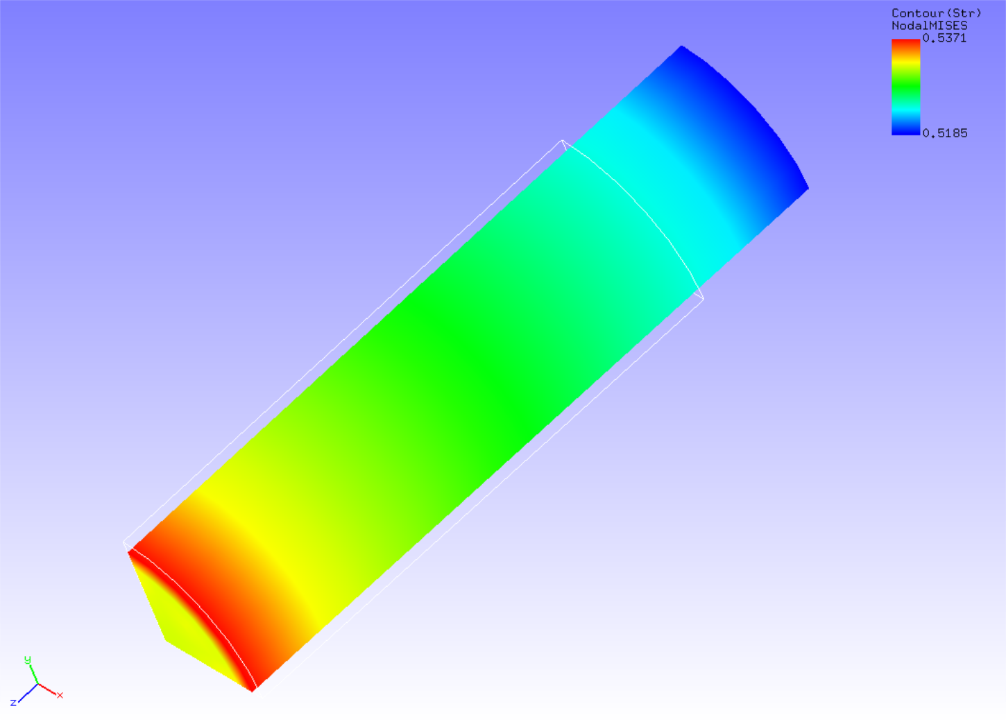
Fig. 4.3.3: Analysis results of deformation and Mises stress
Log file 0.log
 fstr_setup: OK
#### Result step=     0
 ##### Local Summary @Node    :Max/IdMax/Min/IdMin####
 //U1    0.0000E+00         1  0.0000E+00         1
 //U2    0.0000E+00         1  0.0000E+00         1
 //U3    0.0000E+00         1  0.0000E+00         1
 //E11   0.0000E+00         1  0.0000E+00         1
 //E22   0.0000E+00         1  0.0000E+00         1
 //E33   0.0000E+00         1  0.0000E+00         1
 //E12   0.0000E+00         1  0.0000E+00         1
 //E23   0.0000E+00         1  0.0000E+00         1
 //E31   0.0000E+00         1  0.0000E+00         1
 //S11   0.0000E+00         1  0.0000E+00         1
 //S22   0.0000E+00         1  0.0000E+00         1
 //S33   0.0000E+00         1  0.0000E+00         1
 //S12   0.0000E+00         1  0.0000E+00         1
 //S23   0.0000E+00         1  0.0000E+00         1
 //S31   0.0000E+00         1  0.0000E+00         1
 //SMS   0.0000E+00         1  0.0000E+00         1
 ##### Local Summary @Element :Max/IdMax/Min/IdMin####
 //E11   0.0000E+00         1  0.0000E+00         1
 //E22   0.0000E+00         1  0.0000E+00         1
 //E33   0.0000E+00         1  0.0000E+00         1
 //E12   0.0000E+00         1  0.0000E+00         1
 //E23   0.0000E+00         1  0.0000E+00         1
 //E31   0.0000E+00         1  0.0000E+00         1
 //S11   0.0000E+00         1  0.0000E+00         1
 //S22   0.0000E+00         1  0.0000E+00         1
 //S33   0.0000E+00         1  0.0000E+00         1
 //S12   0.0000E+00         1  0.0000E+00         1
 //S23   0.0000E+00         1  0.0000E+00         1
 //S31   0.0000E+00         1  0.0000E+00         1
 //SMS   0.0000E+00         1  0.0000E+00         1
 ##### Global Summary @Node    :Max/IdMax/Min/IdMin####
 //U1    0.0000E+00         1  0.0000E+00         1
 //U2    0.0000E+00         1  0.0000E+00         1
 //U3    0.0000E+00         1  0.0000E+00         1
 //E11   0.0000E+00         1  0.0000E+00         1
 //E22   0.0000E+00         1  0.0000E+00         1
 //E33   0.0000E+00         1  0.0000E+00         1
 //E12   0.0000E+00         1  0.0000E+00         1
 //E23   0.0000E+00         1  0.0000E+00         1
 //E31   0.0000E+00         1  0.0000E+00         1
 //S11   0.0000E+00         1  0.0000E+00         1
 //S22   0.0000E+00         1  0.0000E+00         1
 //S33   0.0000E+00         1  0.0000E+00         1
 //S12   0.0000E+00         1  0.0000E+00         1
 //S23   0.0000E+00         1  0.0000E+00         1
 //S31   0.0000E+00         1  0.0000E+00         1
 //SMS   0.0000E+00         1  0.0000E+00         1
 ##### Global Summary @Element :Max/IdMax/Min/IdMin####
 //E11   0.0000E+00         1  0.0000E+00         1
 //E22   0.0000E+00         1  0.0000E+00         1
 //E33   0.0000E+00         1  0.0000E+00         1
 //E12   0.0000E+00         1  0.0000E+00         1
 //E23   0.0000E+00         1  0.0000E+00         1
 //E31   0.0000E+00         1  0.0000E+00         1
 //S11   0.0000E+00         1  0.0000E+00         1
 //S22   0.0000E+00         1  0.0000E+00         1
 //S33   0.0000E+00         1  0.0000E+00         1
 //S12   0.0000E+00         1  0.0000E+00         1
 //S23   0.0000E+00         1  0.0000E+00         1
 //S31   0.0000E+00         1  0.0000E+00         1
 //SMS   0.0000E+00         1  0.0000E+00         1

 ...

#### Result step=     5
 ##### Local Summary @Node    :Max/IdMax/Min/IdMin####
 //U1    0.0000E+00         1 -6.7543E-01        90
 //U2    0.0000E+00         1 -6.7543E-01        89
 //U3    0.0000E+00         1 -7.0000E+00        38
 //E11  -1.0781E-01        38 -1.1448E-01         7
 //E22  -1.0781E-01        50 -1.1448E-01        13
 //E33   2.3916E-01         7  2.2715E-01        50
 //E12   8.9609E-04        53 -9.2501E-04        10
 //E23   1.0074E-07        38 -2.6232E-03        86
 //E31   1.0074E-07        50 -2.6232E-03        93
 //S11   2.7292E-03        14 -2.6468E-03        49
 //S22   2.7292E-03         6 -2.6468E-03        39
 //S33   8.5422E-01         7  8.1021E-01        50
 //S12   1.2861E-03        53 -1.3373E-03        10
 //S23   1.4289E-07        38 -3.1695E-03        86
 //S31   1.4289E-07        50 -3.1695E-03        93
 //SMS   8.5307E-01         7  8.1134E-01        50
 ##### Local Summary @Element :Max/IdMax/Min/IdMin####
 //E11  -1.0817E-01       759 -1.1410E-01       354
 //E22  -1.0817E-01       768 -1.1410E-01       363
 //E33   2.3863E-01       354  2.2766E-01       759
 //E12   7.4078E-04       766 -7.5734E-04       360
 //E23  -2.5376E-05       753 -2.4790E-03       471
 //E31  -2.5376E-05       749 -2.4790E-03       462
 //S11   2.8994E-03       363 -2.8080E-03       768
 //S22   2.8994E-03       354 -2.8080E-03       759
 //S33   8.5295E-01       354  8.1143E-01       759
 //S12   1.0634E-03       766 -1.0947E-03       360
 //S23  -3.0682E-05       753 -2.9954E-03       471
 //S31  -3.0682E-05       749 -2.9954E-03       462
 //SMS   8.5118E-01       354  8.1315E-01       759
 ##### Global Summary @Node    :Max/IdMax/Min/IdMin####
 //U1    0.0000E+00         1 -6.7543E-01        90
 //U2    0.0000E+00         1 -6.7543E-01        89
 //U3    0.0000E+00         1 -7.0000E+00        38
 //E11  -1.0781E-01        38 -1.1448E-01         7
 //E22  -1.0781E-01        50 -1.1448E-01        13
 //E33   2.3916E-01         7  2.2715E-01        50
 //E12   8.9609E-04        53 -9.2501E-04        10
 //E23   1.0074E-07        38 -2.6232E-03        86
 //E31   1.0074E-07        50 -2.6232E-03        93
 //S11   2.7292E-03        14 -2.6468E-03        49
 //S22   2.7292E-03         6 -2.6468E-03        39
 //S33   8.5422E-01         7  8.1021E-01        50
 //S12   1.2861E-03        53 -1.3373E-03        10
 //S23   1.4289E-07        38 -3.1695E-03        86
 //S31   1.4289E-07        50 -3.1695E-03        93
 //SMS   8.5307E-01         7  8.1134E-01        50
 ##### Global Summary @Element :Max/IdMax/Min/IdMin####
 //E11  -1.0817E-01       759 -1.1410E-01       354
 //E22  -1.0817E-01       768 -1.1410E-01       363
 //E33   2.3863E-01       354  2.2766E-01       759
 //E12   7.4078E-04       766 -7.5734E-04       360
 //E23  -2.5376E-05       753 -2.4790E-03       471
 //E31  -2.5376E-05       749 -2.4790E-03       462
 //S11   2.8994E-03       363 -2.8080E-03       768
 //S22   2.8994E-03       354 -2.8080E-03       759
 //S33   8.5295E-01       354  8.1143E-01       759
 //S12   1.0634E-03       766 -1.0947E-03       360
 //S23  -3.0682E-05       753 -2.9954E-03       471
 //S31  -3.0682E-05       749 -2.9954E-03       462
 //SMS   8.5118E-01       354  8.1315E-01       759