Element Library and Material Data
Element Library and Material Data
Element Library
In FrontISTR, the element groups shows in Table 4.1.1 can be used for analysis. Since HEC-MW is used to input the mesh data into FrontISTR, the following descriptions of the element library is based on the description of HEC-MW. The element library is shown in Figure 4.1.1, and element connectivity and the definitions of the surface number are shown in Figure 4.1.2.
Table 4.1.1: Element Library List
| Element Types | Element No. | Description |
|---|---|---|
| Line element | 111 | Two node link element |
| 112 | Three node link element | |
| Plane element | 231 | Three node triangular element |
| 232 | Six node triangular quadratic element | |
| 241 | Four node quadrilateral element | |
| 242 | Eight node quadrilateral quadratic elment | |
| Solid element | 301 | Two node truss element |
| 341 | Four node tetrahedral element | |
| 342 | Ten node tetrahedral quadratic element | |
| 351 | Six node pentahedral element | |
| 352 | Fifteen node pentahedral quadratic element | |
| 361 | Eight node hexahedral element | |
| 362 | Twenty node hexahedral quadratic element | |
| Interface element | 541 | Quadrilateral cross section linear element |
| 542 | Quadrilateral cross section quadratic element | |
| Beam element | 611 | Two node beam element |
| 641 | Two node beam element (with four 3-dof nodes) | |
| Shell element | 731 | Three node three-dimensional linear element |
| 732 | Six node three-dimensional quadratic element | |
| 741 | Four node three-dimensional linear element | |
| 743 | Nine node three-dimensional quadratic element | |
| 761 | Three node three-dimensional linear element (with six 3-dof nodes) | |
| 781 | Four node three-dimensional linear element (with eight 3-dof nodes) |
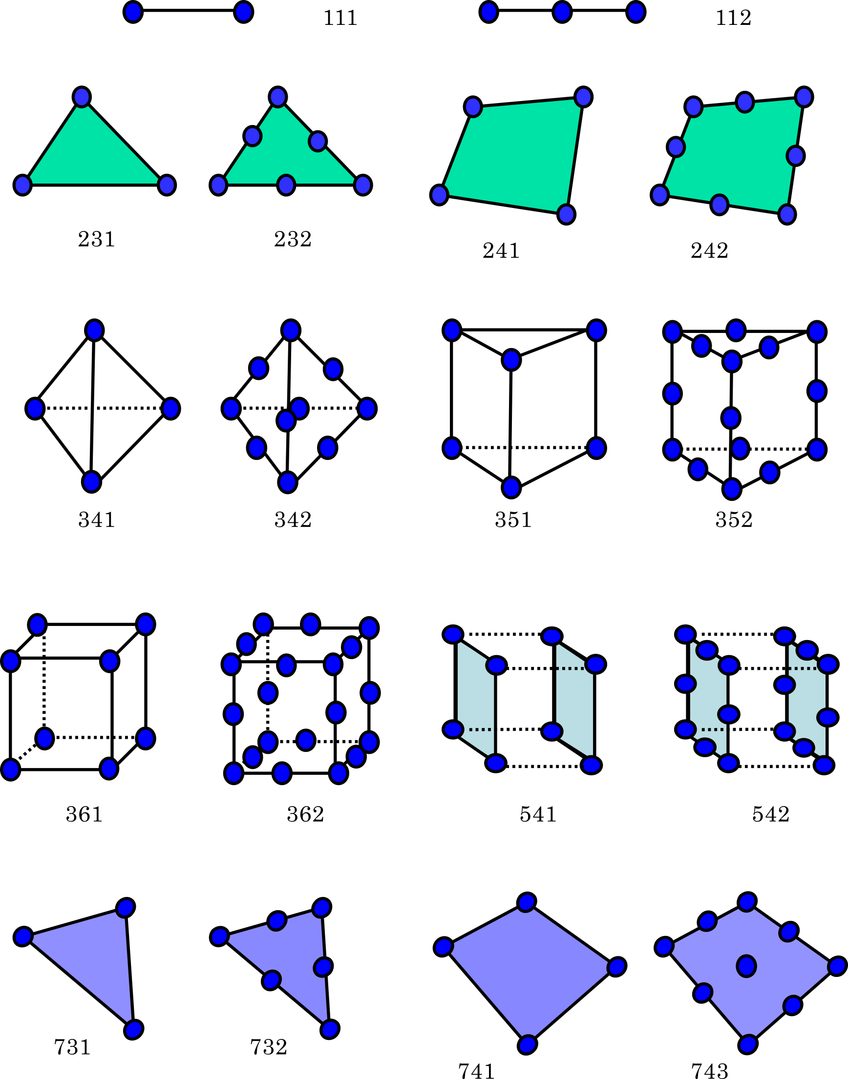
Figure 4.1.1: Element Library
(Line Element)

(Triangular Plane Element)
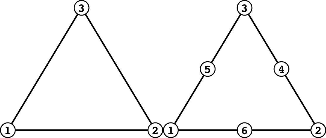
| Surface No. | Linear | Quadratic |
|---|---|---|
| 1 | 1 - 2 | 1 - 6 - 2 |
| 2 | 2 - 3 | 2 - 4 - 3 |
| 3 | 3 - 1 | 3 - 5 - 1 |
(Quadrilateral Plane Element)
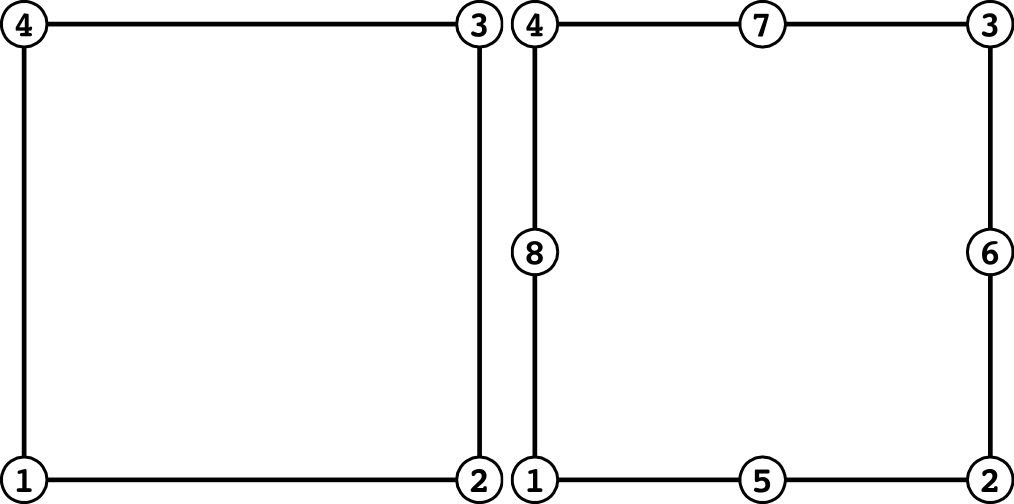
| Surface No. | Linear | Quadratic |
|---|---|---|
| 1 | 1 - 2 | 1 - 5 - 2 |
| 2 | 2 - 3 | 2 - 6 - 3 |
| 3 | 3 - 4 | 3 - 7 - 4 |
| 4 | 4 - 1 | 4 - 8 - 1 |
(Tetrahedral Element)
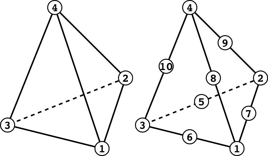
| Surface No. | Linear | Quadratic |
|---|---|---|
| 1 | 1 - 2 - 3 | 1 - 7 - 2 - 5 - 3 - 6 |
| 2 | 1 - 2 - 4 | 1 - 7 - 2 - 9 - 4 - 8 |
| 3 | 2 - 3 - 4 | 2 - 5 - 3 - 10 - 4 - 9 |
| 4 | 3 - 1 - 4 | 3 - 6 - 1 - 10 - 4 - 8 |
(Pentahedral Element)
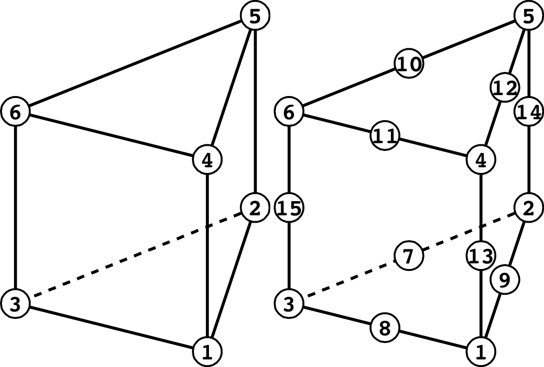
| Surface No. | Linear | Quadratic |
|---|---|---|
| 1 | 1 - 2 - 3 | 1 - 9 - 2 - 7 - 3 - 8 |
| 2 | 4 - 5 - 6 | 4 - 12 - 5 - 10 - 6 - 11 |
| 3 | 1 - 2 - 5 - 4 | 1 - 9 - 2 - 14 - 5 - 12 - 4 - 13 |
| 4 | 2 - 3 - 6 - 5 | 2 - 7 - 3 - 15 - 6 - 10 - 5 - 14 |
| 5 | 3 - 1 - 4 - 6 | 3 - 8 - 1 - 13 - 4 - 11 - 6 - 15 |
(Hexahedral Element)
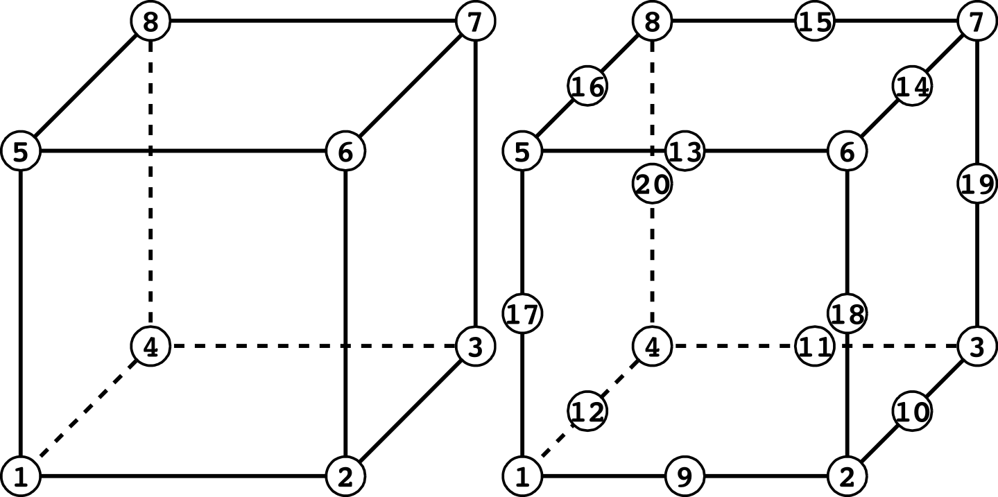
| Surface No. | Linear | Quadratic |
|---|---|---|
| 1 | 1 - 2 - 3 - 4 | 1 - 9 - 2 - 10 - 3 - 11 - 4 - 12 |
| 2 | 5 - 6 - 7 - 8 | 5 - 13 - 6 - 14 - 7 - 15 - 8 - 16 |
| 3 | 1 - 2 - 6 - 5 | 1 - 9 - 2 - 18 - 6 - 13 - 5 - 17 |
| 4 | 2 - 3 - 7 - 6 | 2 - 10 - 3 - 19 - 7 - 14 - 6 - 18 |
| 5 | 3 - 4 - 8 - 7 | 3 - 11 - 4 - 20 - 8 - 15 - 7 - 19 |
| 6 | 4 - 1 - 5 - 8 | 4 - 12 - 1 - 17 - 5 - 16 - 8 - 20 |
(Beam Element)

(Beam Element with 3-dof nodes)

Nodes 1 and 2 for translational DOF, nodes 3 and 4 for rotational DOF.
(Triangular Shell Element)
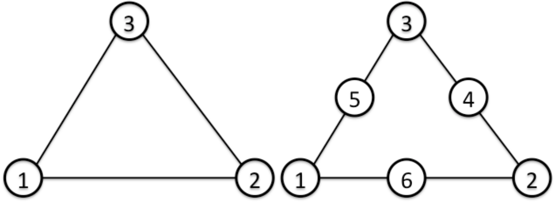
| Surface No. | Linear | Quadratic |
|---|---|---|
| 1 | 1 - 2 - 3 [front] | 1 - 6 - 2 - 4 - 3 - 5 [front] |
| 2 | 3 - 2 - 1 [back] | 3 - 4 - 2 - 6 - 1 - 5 [back] |
(Triangular Shell Element with 3-dof nodes)
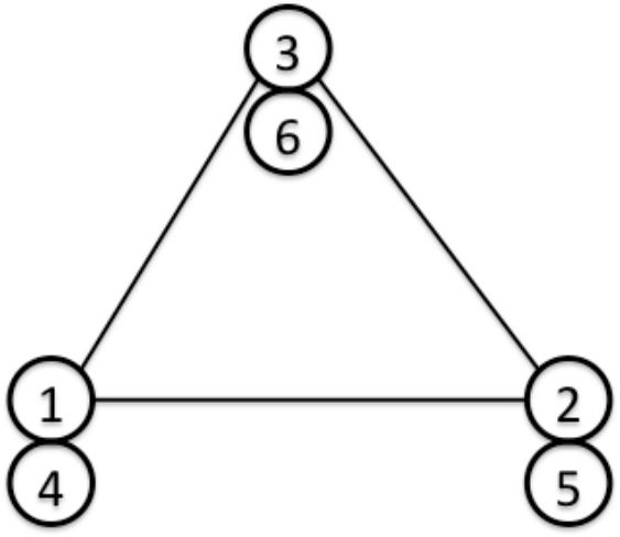
Node 1, 2 and 3 for translational DOF, nodes 4, 5 and 6 for rotational DOF.
| Surface No. | Linear |
|---|---|
| 1 | 1 - 2 - 3 [front] |
| 2 | 3 - 2 - 1 [back] |
(Quadrilateral Shell Element)
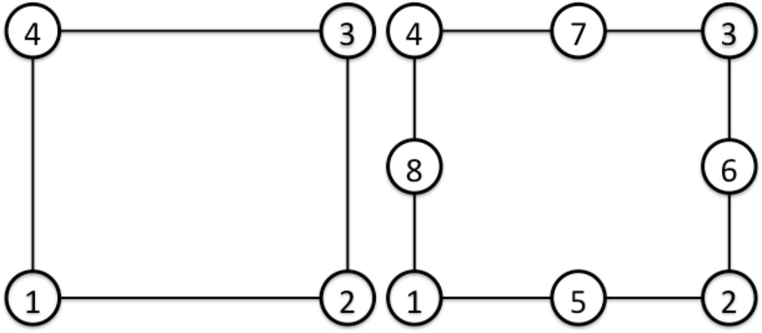
| Surface No. | Linear | Quadratic |
|---|---|---|
| 1 | 1 - 2 - 3 - 4 [front] | 1 - 5 - 2 - 6 - 3 - 7 - 4 - 8 [front] |
| 2 | 4 - 3 - 2 - 1 [back] | 4 - 7 - 3 - 6 - 2 - 5 - 1 - 8 [back] |
(Quadrilateral shell Element with 3-dof nodes)
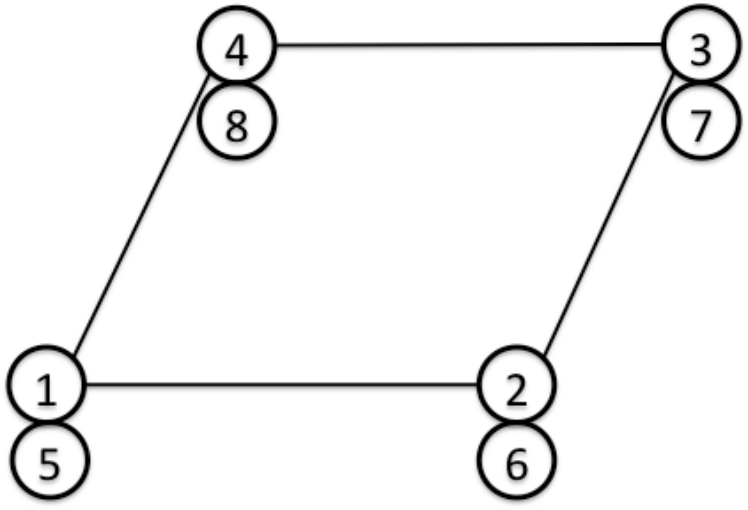
Nodes 1, 2, 3 and 4 for translational DOF, nodes 5, 6, 7 and 8 for rotational DOF.
| Surface No. | Linear |
|---|---|
| 1 | 1 - 2 - 3 - 4 [front] |
| 2 | 4 - 3 - 2 - 1 [back] |
Figure 4.1.2: Connectivity and Surface Number
Material Data
Elastic Static Analysis, Linear Dynamic Analysis and Eigenvalue Analysis
In the elastic static analysis and eigenvalue analysis of FrontISTR, it is necessary to use isotropic elastic material and define the Young's modulus, Poisson's ratio density and the coefficient of linear expansion for each element. The property value of these materials is defined in the header !SECTION and !MATERIAL of the data. An example of the definition is in the following.
(Example)
!! Definition of SECTION
!SECTION,TYPE=SOLID,EGRP=ALL,MATERIAL=M1
In the above !SECTION, the material data name of the element belonging to the group name=ALL in the solid type element is defined as M1.
Next, the definition method of the material data is shown in the following.
(Example)
!! Intention of defining three types of property values in the material name M1
!MATERIAL,NAME=M1,ITEM=3

!! Young's modulus and Poisson's ratio are defined in !ITEM=1 (mandatory)
!ITEM=1,SUBITEM=2
 4000.0,0.3

!! The mass density must be defined in !ITEM=2 (mandatory in the case of ITEM=3)
!ITEM=2
 8.0102E-10

!! The coefficient of linear expansion must be defined in !ITEM=3
!ITEM=3
 1.0E-5
As long as each item number and the type of physical property are compatible, and the ITEM number is correct, it can be defined in any order. However, ITEM=1 must be defined in the order of the Young's modulus and Poisson's ratio.
Heat Conduction Analysis
In the heat conduction analysis of FrontISTR, isotropic material taking into consideration the temperature dependency can be used. Regarding the property values to be defined, the density, specific heat and thermal conductivity are defined for the link, plane surface, solid and shell element, and the gap heat transfer coefficient and the gap radiation factor are defined in the interface element. An example of the definition method of these property values is shown in the following.
(1) In the case of link, plane surface and solid element
Defined in the !SECTION and !MATERIAL header.
(Example)
!! Definition of section
!SECTION,TYPE=SOLID,EGRP=ALL,MATERIAL=M1
In the above !SECTION, the material data name of the element belonging to the group name=ALL in the solid type element is defined as M1. The following shows the definition method of the material data.
(Example)
!! Intension of defining three types of property values
!! in the material of material name M1
!MATERIAL,NAME=M1,ITEM=3

!! The density and temperature are defined in !ITEM=1 (mandatory)
!ITEM=1,SUBITEM=1
 7850., 300.
 7790., 500.
 7700., 800.

!! The specific heat and temperature are defined in !ITEM=2 (mandatory)
!ITEM=2
 0.465, 300.
 0.528, 500.
 0.622, 800.

!! The thermal conductivity and temperature are defined in !ITEM=3 (mandatory)
!ITEM=3
 43., 300.
 38.6, 500.
 27.7, 800.
Since the type of physical properties are identified by each item number in FrontISTR, it can be defined in any order as long as both are consistent.
(2) In the case of an interface element
Defined in the !SECTION header. (Material data is not required)
(Example)
!! Definition of section
!SECTION,TYPE=INTERFACE,EGRP=GAP
 1.0, 20.15, 8.99835E-9, 8.99835E-9
In the above !SECTION, the gap parameter of the element belonging to the group name=GAP in the interface element is defined.
- 1st parameter : Gap width
- 2nd parameter : Gap heat transfer coefficient
- 3rd parameter : Gap radiation factor 1
- 4th parameter : Gap radiation factor 2
(3) In the case of a shell element
Defined in the !SECTION and MATERIAL header.
(Example)
!! Definition of section
!SECTION, TYPE=SHELL, EGRP=SH, MATERIAL=M2
 10.0, 5
In the above !SECTION, the shell characteristics of the element belonging to the group name=SH in the shell type element is defined.
- 1st parameter : Shell thickness
- 2nd parameter : Integration points in the thickness direction
This also means that the material data name of the material physical properties of the element which belong to this group is defined as M2.
For single layered isotropic shell, the definition method of the material physical properties is the same as in the case of the solid element. Refer to the description of the solid element.
In addition, another definition method stated below is available for multi-layered and/or orthotropic shell.
(Example) Isotropic, single-layered shell
!MATERIAL, NAME=M1, ITEM=1
!ITEM=1,SUBITEM=4
 0, 200000, 0.3, 2.0
- 1st parameter : 0=isotropic
- 2nd parameter : Young’s modulus
- 3rd parameter : Poisson’s ratio
- 4th parameter : Shell thickness
(Example) Isotropic, double-layered shell
!MATERIAL, NAME=M1, ITEM=1
!ITEM=1,SUBITEM=7
 0, 200000, 0.3, 2.0, 200000, 0.3, 2.0
- 1st parameter : 0=isotropic
- 2nd parameter : Young’s modulus (1st layer)
- 3rd parameter : Poisson’s ratio (1st layer)
- 4th parameter : Shell thickness (1st layer)
- 5th parameter : : Young’s modulus (2nd layer)
- 6th parameter : Poisson’s ratio (2nd layer)
- 7th parameter : Shell thickness (2nd layer)
By specifying as many material constants as needed for the number of layers, the material is automatically treated as multi-layered shell. The total thickness of the shell is the sum of the thickness of all the layers. The layers are ordered from the top surface of the shell with respect to the normal direction.
(Example) Orthotropic, single-layered shell
!MATERIAL, NAME=M1, ITEM=1
!ITEM=1, SUBITEM=9
 1, 28600., 0.15, 32.3 , 28600., 12434., 12434., 12434., 0.0
- 1st parameter : 1=orthotropic
- 2nd parameter : Young’s modulus E1
- 3rd parameter : Poisson’s ratio n12
- 4th parameter : Shell thickness
- 5th parameter : : Young’s modulus E2
- 6th parameter : Shear modulus G12
- 7th parameter : Shear modulus G23
- 8th parameter : Shear modulus G13
- 9th parameter : Orthotropy angle θ
Orthotropy angle is specified in θ [degree].
(Example) Orthotropic, double-layered shell
!MATERIAL, NAME=M1, ITEM=1
!ITEM=1, SUBITEM=17
 1, 28600., 28600., 0.15, 32.3 , 12434., 12434., 28600., 12434., 12434., 12434., 0.0
- 1st parameter : 1=orthotropic
- 2nd parameter : Young’s modulus E1 (1st layer)
- 3rd parameter : Poisson’s ratio n12 (1st layer)
- 4th parameter : Shell thickness (1st layer)
- 5th parameter : : Young’s modulus E2 (1st layer)
- 6th parameter : Shear modulus G12 (1st layer)
- 7th parameter : Shear modulus G23 (1st layer)
- 8th parameter : Shear modulus G13 (1st layer)
- 9th parameter : Orthotropy angle q (1st layer)
- 10th parameter : Young’s modulus E1 (2nd layer)
- 11th parameter : Poisson’s ratio n12 (2nd layer)
- 12th parameter : Shell thickness (2nd layer)
- 13th parameter : Young’s modulus E2 (2nd layer)
- 14th parameter : Shear modulus G12 (2nd layer)
- 15th parameter : Shear modulus G23 (2nd layer)
- 16th parameter : Shear modulus G13 (2nd layer)
- 17th parameter : Orthotropy angle θ (2nd layer)
Nonelinear Static Analysis
In the nonlinear static analysis of FrontISTR, in addition to the method to define the !SECTION and !MATERIAL shown in item 4.2.1, !ELASTIC, !HYPERELASTIC, !PLASTIC and etc. in the analysis control data can also be defined. An example of the definition is shown in the following.
(Example) Definition of hyperelastic material
!MATERIAL

!! Definition of the Neo Hooke hyperelastic material
!HYPERELASTIC, TYPE=NEOHOOKE

!! C_10 and D are defined (mandatory)
 1000.0, 0.00005
(Example) Definition of the elastoplastic material
!MATERIAL

!! Definition of the isotropic elastic material
!ELASTIC, TYPE=ISOTROPIC

!! The Young's modulus and the Poisson's ratio are defined (mandatory)
 21000.0, 0.3

!! Definition of the Drucker-Prager plastic material
!PLASTIC, TYPE=DRUCKER-PRAGER

!! Viscosity, angle of friction and hardening factor are defined (mandatory)
 500.0, 4.0, 10.0