Contact Analysis (Part 2)
Contact Analysis (Part 2)
This analysis uses the data of tutorial/10_contact_2tubes.
Analysis target
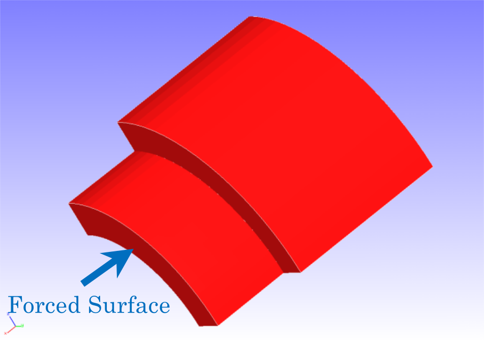
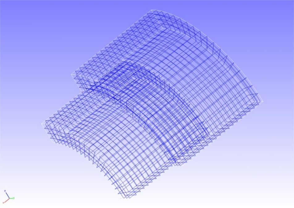
The analysis is a cylindrical indentation problem, and the geometry of the analysis target is shown in Figure 4.10.1 and the mesh data is shown in Figure 4.10.2.
| Item | Description | Notes | Reference |
|---|---|---|---|
| Type of analysis | Non-linear static analysis(elastic,contact) | !SOLUTION,TYPE=NLSTATIC !CONTACT | |
| Number of nodes | 4,000 | ||
| Number of elements | 2,888 | ||
| Element type | Eight node hexahedral element | !ELEMENT,TYPE=361 | |
| Material name | M1 | !MATERIAL,NAME=M1 | |
| Material property | ELASTIC | !ELASTIC | |
| Boundary conditions | Restraint,Forced displacement | ||
| Matrix solution | Direct method | !!SOLVER,METHOD=MUMPS |

Fig. 4.10.1: Shape of the analysis target

Fig. 4.10.2: Mesh data of the analysis target
Analysis content
The Lagrangian multiplier method is used to perform contact analysis to give the forced displacement in the push-in direction to the forced surface shown in Figure 4.10.1. The analytical control data is shown below.
Analysis control data 2tubes.cnt.
#  Control File for FISTR
## Analysis Control
!VERSION
 3
!SOLUTION, TYPE=NLSTATIC
!WRITE,RESULT
!WRITE,VISUAL
## Solver Control
### Boundary Conditon
!BOUNDARY, GRPID=1
  X0, 1, 3, 0.0
  Y0, 2, 2, 0.0
  Z0, 3, 3, 0.0
!BOUNDARY, GRPID=2
  X1, 1, 1, 0.0
!BOUNDARY, GRPID=3
  X1, 1, 1, -1.0
!CONTACT_ALGO, TYPE=SLAGRANGE
!CONTACT, GRPID=1, INTERACTION=FSLID, NPENALTY=1.0e+2
  CP1, 0.0, 1.0e+5
### STEP
!STEP, SUBSTEPS=4, CONVERG=1.0e-5
 BOUNDARY, 1
 BOUNDARY, 3
 CONTACT, 1
### Material
!MATERIAL, NAME=M1
!ELASTIC
 2.1e+5, 0.3
### Solver Setting
!SOLVER,METHOD=MUMPS
## Post Control
!VISUAL,metod=PSR
!surface_num=1
!surface 1
!output_type=VTK
!END
Analysis procedure
Execute the FrontISTR execution command fistr1.
$ cd FrontISTR/tutorial/10_contact_2tubes
$ fistr1 -t 4
(Runs in 4 threads.)
Analysis results
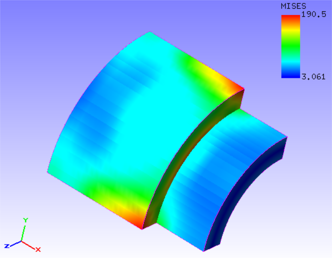
The results of the fourth substep are shown in Figure 4.10.3. A deformation diagram with Mises stress contours is created by REVOCAP_PrePost. A part of the analysis results log file is shown below as numerical data for the analysis results.

Fig. 4.10.3: Analysis results of deformation and Mises stress
Log file 0.log.
 fstr_setup: OK
#### Result step=     0
 ##### Local Summary @Node    :Max/IdMax/Min/IdMin####
 //U1    0.0000E+00         1  0.0000E+00         1
 //U2    0.0000E+00         1  0.0000E+00         1
 //U3    0.0000E+00         1  0.0000E+00         1
 //E11   0.0000E+00         1  0.0000E+00         1
 //E22   0.0000E+00         1  0.0000E+00         1
 //E33   0.0000E+00         1  0.0000E+00         1
 //E12   0.0000E+00         1  0.0000E+00         1
 //E23   0.0000E+00         1  0.0000E+00         1
 //E31   0.0000E+00         1  0.0000E+00         1
 //S11   0.0000E+00         1  0.0000E+00         1
 //S22   0.0000E+00         1  0.0000E+00         1
 //S33   0.0000E+00         1  0.0000E+00         1
 //S12   0.0000E+00         1  0.0000E+00         1
 //S23   0.0000E+00         1  0.0000E+00         1
 //S31   0.0000E+00         1  0.0000E+00         1
 //SMS   0.0000E+00         1  0.0000E+00         1
 ##### Local Summary @Element :Max/IdMax/Min/IdMin####
 //E11   0.0000E+00         1  0.0000E+00         1
 //E22   0.0000E+00         1  0.0000E+00         1
 //E33   0.0000E+00         1  0.0000E+00         1
 //E12   0.0000E+00         1  0.0000E+00         1
 //E23   0.0000E+00         1  0.0000E+00         1
 //E31   0.0000E+00         1  0.0000E+00         1
 //S11   0.0000E+00         1  0.0000E+00         1
 //S22   0.0000E+00         1  0.0000E+00         1
 //S33   0.0000E+00         1  0.0000E+00         1
 //S12   0.0000E+00         1  0.0000E+00         1
 //S23   0.0000E+00         1  0.0000E+00         1
 //S31   0.0000E+00         1  0.0000E+00         1
 //SMS   0.0000E+00         1  0.0000E+00         1
 ##### Global Summary @Node    :Max/IdMax/Min/IdMin####
 //U1    0.0000E+00         1  0.0000E+00         1
 //U2    0.0000E+00         1  0.0000E+00         1
 //U3    0.0000E+00         1  0.0000E+00         1
 //E11   0.0000E+00         1  0.0000E+00         1
 //E22   0.0000E+00         1  0.0000E+00         1
 //E33   0.0000E+00         1  0.0000E+00         1
 //E12   0.0000E+00         1  0.0000E+00         1
 //E23   0.0000E+00         1  0.0000E+00         1
 //E31   0.0000E+00         1  0.0000E+00         1
 //S11   0.0000E+00         1  0.0000E+00         1
 //S22   0.0000E+00         1  0.0000E+00         1
 //S33   0.0000E+00         1  0.0000E+00         1
 //S12   0.0000E+00         1  0.0000E+00         1
 //S23   0.0000E+00         1  0.0000E+00         1
 //S31   0.0000E+00         1  0.0000E+00         1
 //SMS   0.0000E+00         1  0.0000E+00         1
 ##### Global Summary @Element :Max/IdMax/Min/IdMin####
 //E11   0.0000E+00         1  0.0000E+00         1
 //E22   0.0000E+00         1  0.0000E+00         1
 //E33   0.0000E+00         1  0.0000E+00         1
 //E12   0.0000E+00         1  0.0000E+00         1
 //E23   0.0000E+00         1  0.0000E+00         1
 //E31   0.0000E+00         1  0.0000E+00         1
 //S11   0.0000E+00         1  0.0000E+00         1
 //S22   0.0000E+00         1  0.0000E+00         1
 //S33   0.0000E+00         1  0.0000E+00         1
 //S12   0.0000E+00         1  0.0000E+00         1
 //S23   0.0000E+00         1  0.0000E+00         1
 //S31   0.0000E+00         1  0.0000E+00         1
 //SMS   0.0000E+00         1  0.0000E+00         1

 ...

#### Result step=     4
 ##### Local Summary @Node    :Max/IdMax/Min/IdMin####
 //U1    8.7136E-04        32 -1.0021E+00      2006
 //U2    8.7633E-03       104 -7.0546E-03      2006
 //U3    8.7634E-03         4 -7.0546E-03      1901
 //E11   7.5985E-04      1901 -4.1250E-04       105
 //E22   9.8385E-04         2 -9.3128E-04      2058
 //E33   9.8386E-04       102 -9.3120E-04      3843
 //E12   5.3544E-04       133 -2.8361E-04       278
 //E23   1.2509E-03      1901 -1.4195E-03         4
 //E31   5.3554E-04        33 -2.8366E-04      1678
 //S11   7.7172E+01       103 -8.9880E+01       101
 //S22   2.0158E+02         2 -2.2918E+02      1905
 //S33   2.0159E+02       102 -2.2920E+02      2010
 //S12   4.3210E+01       133 -2.2913E+01       278
 //S23   1.0057E+02      1901 -1.1446E+02         4
 //S31   4.3219E+01        33 -2.2918E+01      1678
 //SMS   3.0051E+02      1901  3.1670E+00      2454
 ##### Local Summary @Element :Max/IdMax/Min/IdMin####
 //E11   4.3715E-04      2809 -3.1965E-04      1293
 //E22   8.8407E-04        73 -7.9864E-04      1369
 //E33   8.8408E-04      1365 -7.9867E-04      2809
 //E12   5.3226E-04      1324 -1.9554E-04       188
 //E23   1.0836E-03      2149 -1.0974E-03       684
 //E31   5.3223E-04        32 -1.9559E-04      1176
 //S11   6.6688E+01      1296 -7.9313E+01      1293
 //S22   1.8533E+02        73 -2.1547E+02      1369
 //S33   1.8533E+02      1365 -2.1548E+02      2809
 //S12   4.2951E+01      1324 -1.5800E+01       188
 //S23   8.7338E+01      2149 -8.8751E+01       684
 //S31   4.2949E+01        32 -1.5804E+01      1176
 //SMS   1.9064E+02      1369  3.2782E+00      2126
 ##### Global Summary @Node    :Max/IdMax/Min/IdMin####
 //U1    8.7136E-04        32 -1.0021E+00      2006
 //U2    8.7633E-03       104 -7.0546E-03      2006
 //U3    8.7634E-03         4 -7.0546E-03      1901
 //E11   7.5985E-04      1901 -4.1250E-04       105
 //E22   9.8385E-04         2 -9.3128E-04      2058
 //E33   9.8386E-04       102 -9.3120E-04      3843
 //E12   5.3544E-04       133 -2.8361E-04       278
 //E23   1.2509E-03      1901 -1.4195E-03         4
 //E31   5.3554E-04        33 -2.8366E-04      1678
 //S11   7.7172E+01       103 -8.9880E+01       101
 //S22   2.0158E+02         2 -2.2918E+02      1905
 //S33   2.0159E+02       102 -2.2920E+02      2010
 //S12   4.3210E+01       133 -2.2913E+01       278
 //S23   1.0057E+02      1901 -1.1446E+02         4
 //S31   4.3219E+01        33 -2.2918E+01      1678
 //SMS   3.0051E+02      1901  3.1670E+00      2454
 ##### Global Summary @Element :Max/IdMax/Min/IdMin####
 //E11   4.3715E-04      2809 -3.1965E-04      1293
 //E22   8.8407E-04        73 -7.9864E-04      1369
 //E33   8.8408E-04      1365 -7.9867E-04      2809
 //E12   5.3226E-04      1324 -1.9554E-04       188
 //E23   1.0836E-03      2149 -1.0974E-03       684
 //E31   5.3223E-04        32 -1.9559E-04      1176
 //S11   6.6688E+01      1296 -7.9313E+01      1293
 //S22   1.8533E+02        73 -2.1547E+02      1369
 //S33   1.8533E+02      1365 -2.1548E+02      2809
 //S12   4.2951E+01      1324 -1.5800E+01       188
 //S23   8.7338E+01      2149 -8.8751E+01       684
 //S31   4.2949E+01        32 -1.5804E+01      1176
 //SMS   1.9064E+02      1369  3.2782E+00      2126