Non-linear Contact Dynamic Analysis
Non-Linear Contact Dynamic Analysis
This analysis uses the data of tutorial/14_dynamic_plate_contact.
Analysis target
The object of the analysis was the fall impact analysis of a square material on a floor surface, and the geometry is shown in Fig. 4.14.1 and the mesh data is shown in Fig. 4.14.2.
| Item | Description | Notes | Reference |
|---|---|---|---|
| Type of analysis | Nonlinear contact dynamic analysis | !SOLUTION,TYPE=DYNAMIC !DYNAMIC,TYPE=NONLINEAR !CONTACT | |
| Number of nodes | 10,712 | ||
| Number of elements | 8,232 | ||
| Element type | Eight node hexahedral element | !ELEMENT,TYPE=361 | |
| Material name | M1, M2 | !MATERIAL,NAME=M1 !MATERIAL,NAME=M2 | |
| Material property | ELASTIC, PLASTIC | !ELASTIC !PLASTIC | |
| Boundary conditions | Restraint, Initial velocity | !VELOCITY,TYPE=INITIAL | |
| Matrix solution | Direct method | !SOLVER,METHOD=MUMPS |
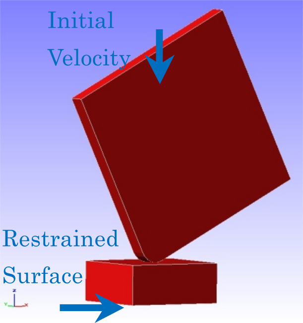
Fig. 4.14.1: Shape of the floor surface and square material
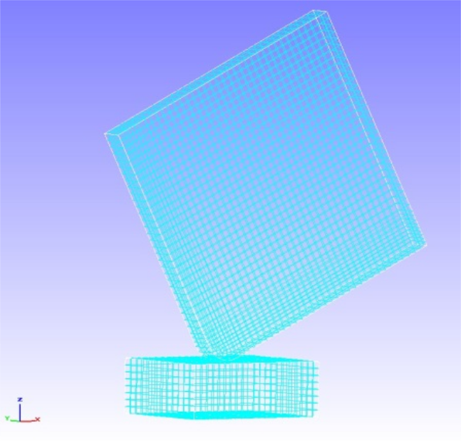
Fig. 4.14.2: Mesh data of the floor surface and square material
Analysis content
The initial speed of 4427 mm/s is set for the square material to be analyzed, and the contact motion analysis is performed. The analysis control data is shown below.
Analysis control data plateToGround.cnt.
!!
!! Control File for FISTR
!!
!VERSION
 3
!WRITE,LOG,FREQUENCY=10
!WRITE,RESULT,FREQUENCY=10
!SOLUTION, TYPE=DYNAMIC
!DYNAMIC, TYPE=NONLINEAR
 1 , 1
 0.0, 1.0, 200, 1.0000e-8
 0.65, 0.330625
 1, 1, 0.0, 0.0
 20, 2621, 1
 1, 1, 1, 1, 1, 1
!BOUNDARY, GRPID = 1
  bottom, 1, 3, 0.0
!VELOCITY, TYPE = INITIAL
  plate, 3, 3, -4427.0
!CONTACT_ALGO, TYPE=SLAGRANGE
!CONTACT, GRPID=1, INTERACTION=FSLID
  CP1, 0.0, 1.0e+5
!STEP, CONVERG=1.0e-8, ITMAX=100
 BOUNDARY, 1
 CONTACT, 1
!MATERIAL, NAME = M1
!ELASTIC
2.00000e+5, 0.3
!PLASTIC
 1.0e+8, 0.0
!MATERIAL, NAME = M2
!ELASTIC
 1.16992e+5, 0.3
!PLASTIC
 70.0, 0.0
!SOLVER,METHOD=MUMPS
!END
Analysis Results
A contour diagram of the Mises stresses during the fall impact is shown in Figure 4.14.3. In addition, a portion of the energy output file (dyna_energy.txt) for the monitoring nodes is shown below as numerical data for the analysis results.
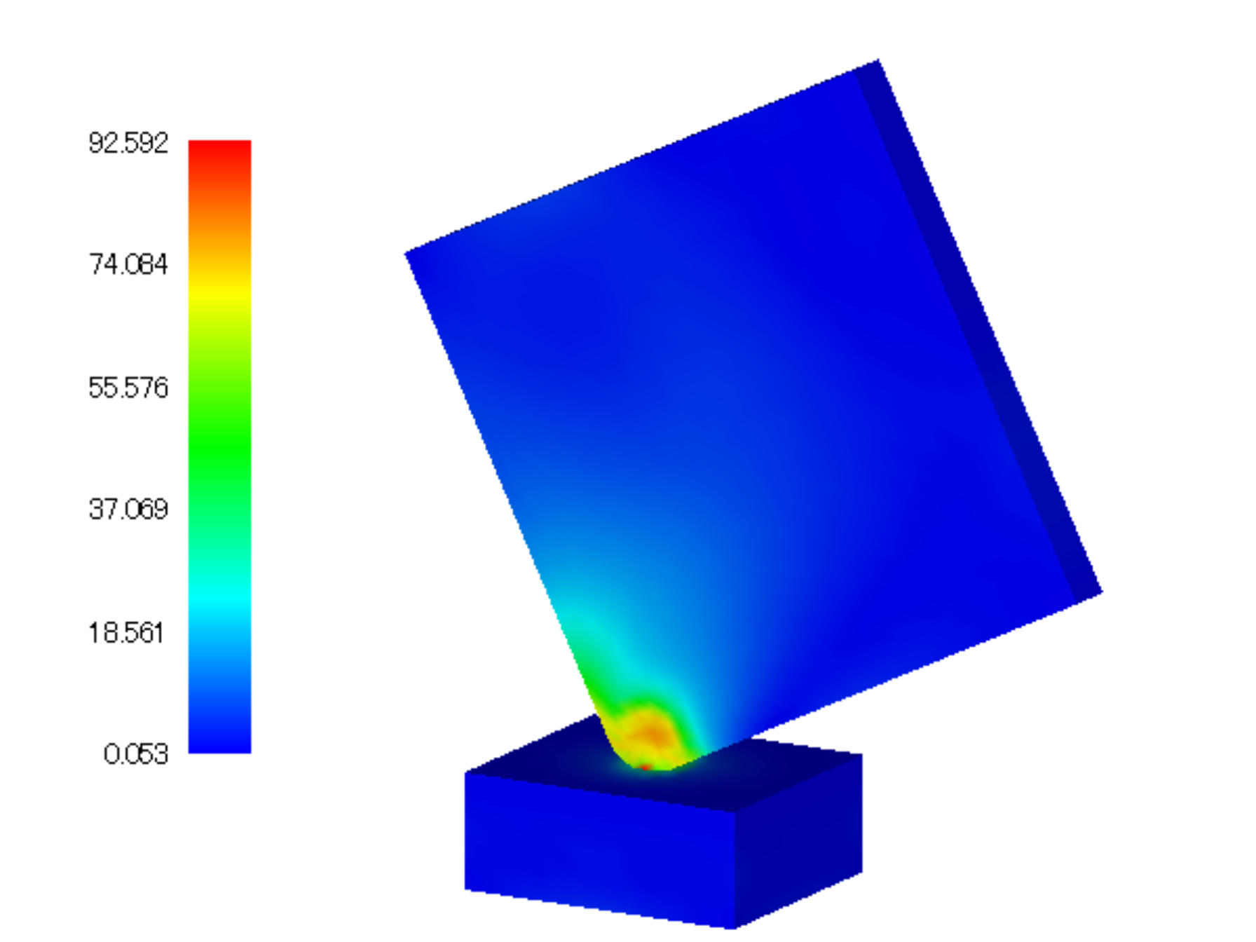
Fig. 4.14.3: Mises stress of the falling impact
Displacement of monitoring nodes dyna_energy.txt.
  time step     time      kinetic energy   strain energy   total energy
         0  0.0000E+000     9.7816E-003     0.0000E+000     9.7816E-003
         1  1.0000E-008     9.7756E-003     4.9470E-006     9.7806E-003
         2  2.0000E-008     9.7654E-003     1.4636E-005     9.7800E-003
         3  3.0000E-008     9.7566E-003     2.2609E-005     9.7792E-003
         4  4.0000E-008     9.7505E-003     3.7965E-005     9.7884E-003
         5  5.0000E-008     9.7425E-003     6.4932E-005     9.8074E-003
         6  6.0000E-008     9.7214E-003     8.4571E-005     9.8060E-003
         7  7.0000E-008     9.7139E-003     9.0613E-005     9.8045E-003
         8  8.0000E-008     9.7184E-003     1.0958E-004     9.8280E-003
         9  9.0000E-008     9.7175E-003     1.5717E-004     9.8747E-003
        10  1.0000E-007     9.6909E-003     1.7998E-004     9.8709E-003
        11  1.1000E-007     9.6917E-003     1.9733E-004     9.8890E-003
        12  1.2000E-007     9.7137E-003     2.2403E-004     9.9377E-003
        13  1.3000E-007     9.6813E-003     2.4397E-004     9.9253E-003
Log file 0.log.
 fstr_setup: OK
#### Result step=    10
 ##### Local Summary @Node    :Max/IdMax/Min/IdMin####
 //U1    7.6111E-05      2780 -1.3733E-04      2807
 //U2    3.5826E-04      2645 -3.5826E-04      2597
 //U3    7.3650E-07      2599 -4.8426E-04      2785
 //V1    1.0743E+03      2780 -2.1388E+03      2785
 //V2    4.1975E+03      2645 -4.1975E+03      2597
 //V3    3.4753E+02      2632 -5.2027E+03      2785
 //A1    1.8419E+10      2797 -1.7512E+10      2790
 //A2    1.6413E+10      2645 -1.6413E+10      2597
 //A3    2.6159E+11      2632 -7.1824E+11      2598
 //E11   5.5643E-03      2798 -3.1738E-03      2785
 //E22   9.6885E-03      2598 -1.4502E-04      2780
 //E33   2.6801E-03      2785 -1.5067E-02      2598
 //E12   5.7146E-03      2778 -5.7146E-03      2782
 //E23   8.8189E-03      2597 -8.8189E-03      2645
 //E31   9.6709E-03      2785 -8.9273E-03      2780
 //S11   2.3553E+01      2890 -6.9294E+01      2621
 //S22   3.9504E+01      2797 -6.4266E+01      2621
 //S33   1.5165E+01      2827 -1.3217E+02      2621
 //S12   1.9751E+01      2778 -1.9751E+01      2782
 //S23   1.9616E+01      2838 -1.9616E+01      2842
 //S31   3.7803E+01      2868 -3.4973E+01      2867
 //SMS   7.7288E+01      2840  1.4896E-13     10709
 ##### Local Summary @Element :Max/IdMax/Min/IdMin####
 //E11   3.3315E-03      2188 -3.5688E-03      2198
 //E22   4.2263E-03      2185 -1.6011E-05      1817
 //E33   2.8970E-03      2198 -7.3958E-03      2185
 //E12   4.8924E-03      2186 -4.8924E-03      2192
 //E23   3.4853E-03      2205 -3.4853E-03      2208
 //E31   1.1270E-02      2187 -9.6668E-03      2188
 //S11   2.6052E+01      2241 -7.3461E+01      2189
 //S22   5.6465E+01      2194 -7.8034E+01      2189
 //S33   7.5395E+01      2194 -1.1968E+02      2189
 //S12   1.3438E+01      2186 -1.3438E+01      2192
 //S23   1.4576E+01      2205 -1.4576E+01      2208
 //S31   3.5356E+01      2217 -3.3931E+01      2220
 //SMS   6.8689E+01      2233  1.4239E-13      8230
 ##### Global Summary @Node    :Max/IdMax/Min/IdMin####
 //U1    7.6111E-05      2780 -1.3733E-04      2807
 //U2    3.5826E-04      2645 -3.5826E-04      2597
 //U3    7.3650E-07      2599 -4.8426E-04      2785
 //V1    1.0743E+03      2780 -2.1388E+03      2785
 //V2    4.1975E+03      2645 -4.1975E+03      2597
 //V3    3.4753E+02      2632 -5.2027E+03      2785
 //A1    1.8419E+10      2797 -1.7512E+10      2790
 //A2    1.6413E+10      2645 -1.6413E+10      2597
 //A3    2.6159E+11      2632 -7.1824E+11      2598
 //E11   5.5643E-03      2798 -3.1738E-03      2785
 //E22   9.6885E-03      2598 -1.4502E-04      2780
 //E33   2.6801E-03      2785 -1.5067E-02      2598
 //E12   5.7146E-03      2778 -5.7146E-03      2782
 //E23   8.8189E-03      2597 -8.8189E-03      2645
 //E31   9.6709E-03      2785 -8.9273E-03      2780
 //S11   2.3553E+01      2890 -6.9294E+01      2621
 //S22   3.9504E+01      2797 -6.4266E+01      2621
 //S33   1.5165E+01      2827 -1.3217E+02      2621
 //S12   1.9751E+01      2778 -1.9751E+01      2782
 //S23   1.9616E+01      2838 -1.9616E+01      2842
 //S31   3.7803E+01      2868 -3.4973E+01      2867
 //SMS   7.7288E+01      2840  1.4896E-13     10709
  ##### Global Summary @Element :Max/IdMax/Min/IdMin####
 //E11   3.3315E-03      2188 -3.5688E-03      2198
 //E22   4.2263E-03      2185 -1.6011E-05      1817
 //E33   2.8970E-03      2198 -7.3958E-03      2185
 //E12   4.8924E-03      2186 -4.8924E-03      2192
 //E23   3.4853E-03      2205 -3.4853E-03      2208
 //E31   1.1270E-02      2187 -9.6668E-03      2188
 //S11   2.6052E+01      2241 -7.3461E+01      2189
 //S22   5.6465E+01      2194 -7.8034E+01      2189
 //S33   7.5395E+01      2194 -1.1968E+02      2189
 //S12   1.3438E+01      2186 -1.3438E+01      2192
 //S23   1.4576E+01      2205 -1.4576E+01      2208
 //S31   3.5356E+01      2217 -3.3931E+01      2220
 //SMS   6.8689E+01      2233  1.4239E-13      8230

 ...

#### Result step=   200
 ##### Local Summary @Node    :Max/IdMax/Min/IdMin####
 //U1    1.0996E-03      2818 -2.9048E-03      2803
 //U2    8.2012E-03      2645 -8.2012E-03      2597
 //U3    1.1800E-06      2465 -8.5895E-03      5373
 //V1    8.9566E+02     10712 -2.1228E+03      2831
 //V2    3.4246E+03      2645 -3.4246E+03      2597
 //V3    3.2884E+02      2794 -4.0108E+03      5377
 //A1    2.1058E+09      9165 -1.2760E+09      4757
 //A2    7.5110E+08      2769 -7.5110E+08      2478
 //A3    4.4278E+09      8975 -1.0747E+09      2465
 //E11   5.4925E-02      2838 -4.1160E-02      2788
 //E22   2.2537E-01      2621 -4.2604E-04      2921
 //E33   1.4576E-02      2815 -2.7463E-01      2621
 //E12   9.7058E-02      2789 -9.7058E-02      2791
 //E23   7.4272E-02      2779 -7.4272E-02      2781
 //E31   1.3776E-01      2785 -1.5350E-01      2780
 //S11   4.2677E+01      3113 -6.9474E+01      2621
 //S22   4.7637E+01      2815 -4.2010E+01      2921
 //S33   1.6261E+01      2853 -1.1496E+02      2780
 //S12   2.2732E+01      2830 -2.2732E+01      2826
 //S23   4.0309E+01      2597 -4.0309E+01      2645
 //S31   3.8697E+01      2913 -3.7722E+01      3054
 //SMS   9.0611E+01      2597  6.2561E-02      9662
 ##### Local Summary @Element :Max/IdMax/Min/IdMin####
 //E11   5.4784E-02      2209 -4.6698E-02      2201
 //E22   1.8822E-01      2188 -7.6612E-05      2323
 //E33   2.2781E-02      2202 -2.2608E-01      2188
 //E12   1.0327E-01      2193 -1.0327E-01      2196
 //E23   4.0800E-02      2210 -4.0800E-02      2211
 //E31   1.3391E-01      2189 -1.7023E-01      2194
 //S11   4.3368E+01      2434 -7.5148E+01      2188
 //S22   6.8745E+01      2203 -4.7855E+01      2048
 //S33   7.0360E+01      2202 -1.1351E+02      2188
 //S12   1.9354E+01      2193 -1.9354E+01      2196
 //S23   1.4194E+01      1796 -1.4194E+01      1754
 //S31   3.8915E+01      2367 -3.3190E+01      2298
 //SMS   6.9701E+01      2187  3.8349E-02      7504
 ##### Global Summary @Node    :Max/IdMax/Min/IdMin####
 //U1    1.0996E-03      2818 -2.9048E-03      2803
 //U2    8.2012E-03      2645 -8.2012E-03      2597
 //U3    1.1800E-06      2465 -8.5895E-03      5373
 //V1    8.9566E+02     10712 -2.1228E+03      2831
 //V2    3.4246E+03      2645 -3.4246E+03      2597
 //V3    3.2884E+02      2794 -4.0108E+03      5377
 //A1    2.1058E+09      9165 -1.2760E+09      4757
 //A2    7.5110E+08      2769 -7.5110E+08      2478
 //A3    4.4278E+09      8975 -1.0747E+09      2465
 //E11   5.4925E-02      2838 -4.1160E-02      2788
 //E22   2.2537E-01      2621 -4.2604E-04      2921
 //E33   1.4576E-02      2815 -2.7463E-01      2621
 //E12   9.7058E-02      2789 -9.7058E-02      2791
 //E23   7.4272E-02      2779 -7.4272E-02      2781
 //E31   1.3776E-01      2785 -1.5350E-01      2780
 //S11   4.2677E+01      3113 -6.9474E+01      2621
 //S22   4.7637E+01      2815 -4.2010E+01      2921
 //S33   1.6261E+01      2853 -1.1496E+02      2780
 //S12   2.2732E+01      2830 -2.2732E+01      2826
 //S23   4.0309E+01      2597 -4.0309E+01      2645
 //S31   3.8697E+01      2913 -3.7722E+01      3054
 //SMS   9.0611E+01      2597  6.2561E-02      9662
 ##### Global Summary @Element :Max/IdMax/Min/IdMin####
 //E11   5.4784E-02      2209 -4.6698E-02      2201
 //E22   1.8822E-01      2188 -7.6612E-05      2323
 //E33   2.2781E-02      2202 -2.2608E-01      2188
 //E12   1.0327E-01      2193 -1.0327E-01      2196
 //E23   4.0800E-02      2210 -4.0800E-02      2211
 //E31   1.3391E-01      2189 -1.7023E-01      2194
 //S11   4.3368E+01      2434 -7.5148E+01      2188
 //S22   6.8745E+01      2203 -4.7855E+01      2048
 //S33   7.0360E+01      2202 -1.1351E+02      2188
 //S12   1.9354E+01      2193 -1.9354E+01      2196
 //S23   1.4194E+01      1796 -1.4194E+01      1754
 //S31   3.8915E+01      2367 -3.3190E+01      2298
 //SMS   6.9701E+01      2187  3.8349E-02      7504