Non-linear Static Analysis (Hyperelasticity, Part 2)
Non-linear Static Analysis (Hyperelasticity, Part 2)
This analysis uses the data of tutorial/04_hyperelastic_spring.
Analysis target
The spring is the object of the analysis, the geometry is shown in Figure 4.4.1 and the mesh data is shown in Figure 4.4.2.
| Item | Description | Notes | Reference |
|---|---|---|---|
| Typo of analysis | Non-linear static analysis | !SOLUTION,TYPE=NLSTATIC | |
| Number of nodes | 78,771 | ||
| Number of elements | 46,454 | ||
| Element type | Ten node tetrahedral quadratic element | !ELEMENT,TYPE=342 | |
| Material name | MAT1 | !MATERIAL,NAME=MAT1 | |
| Material property | HYPERELASTIC | !HYPERELASTIC,TYPE=ARRUDA-BOYCE | |
| Boundary conditions | Restraint, Concentrated force | ||
| Matrix solution | CG/SSOR | !SOLVER,METHOD=CG,PRECOND=1 |
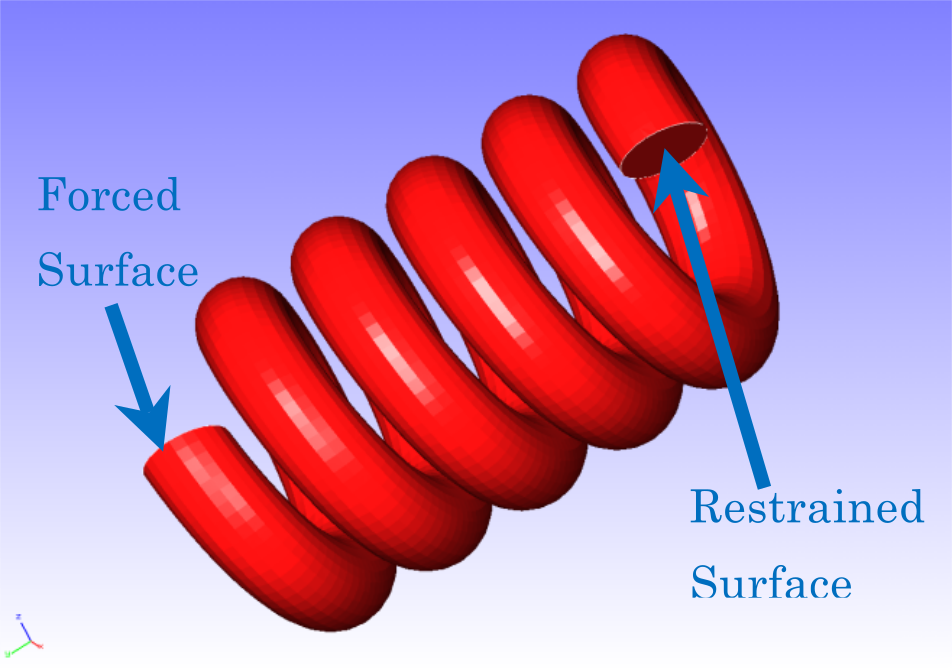
Fig. 4.4.1: Shape of the spring
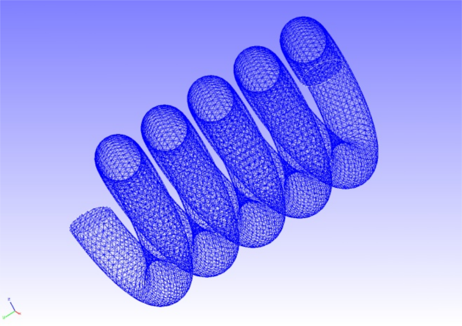
Fig. 4.4.2: Mesh data of the spring
Analysis content
In this stress analysis, the displacement of the constrained surface shown in Fig. 4.4.1 is restrained, and the displacement is given to the forced surface. The Arruda–Boyce model was used in the material constitutive equation of hyperelasticity. The analysis control data are presented below.
Analysis control data spring.cnt
#  Control File for FISTR
## Analysis Control
!VERSION
 3
!SOLUTION, TYPE=NLSTATIC
!WRITE,RESULT
!WRITE,VISUAL
## Solver Control
### Boundary Conditon
!BOUNDARY, GRPID=1
 LOADS, 2, 2, -5.0
 FIX,   1, 3, 0.0
### STEP
!STEP, SUBSTEPS=1, CONVERG=1.0e-5
 BOUNDARY, 1
### Material
!MATERIAL, NAME=MAT1
!HYPERELASTIC, TYPE=ARRUDA-BOYCE
 0.71, 1.7029, 0.1408
### Solver Setting
!SOLVER,METHOD=CG,PRECOND=1,ITERLOG=YES,TIMELOG=YES
 10000, 1
 1.0e-8, 1.0, 0.0
## Post Control
!VISUAL,metod=PSR
!surface_num=1
!surface 1
!output_type=VTK
!END
Analysis procedure
Execute the FrontISTR execution command fistr1.
$ cd FrontISTR/tutorial/04_hyperelastic_spring
$ fistr1 -t 4
(Runs in 4 threads.)
Analysis results
A deformation diagram with a contoured displacement is created by REVOCAP_PrePost and shown in Figure 4.4.3. A part of the log file is shown below as numerical data for the analysis results.
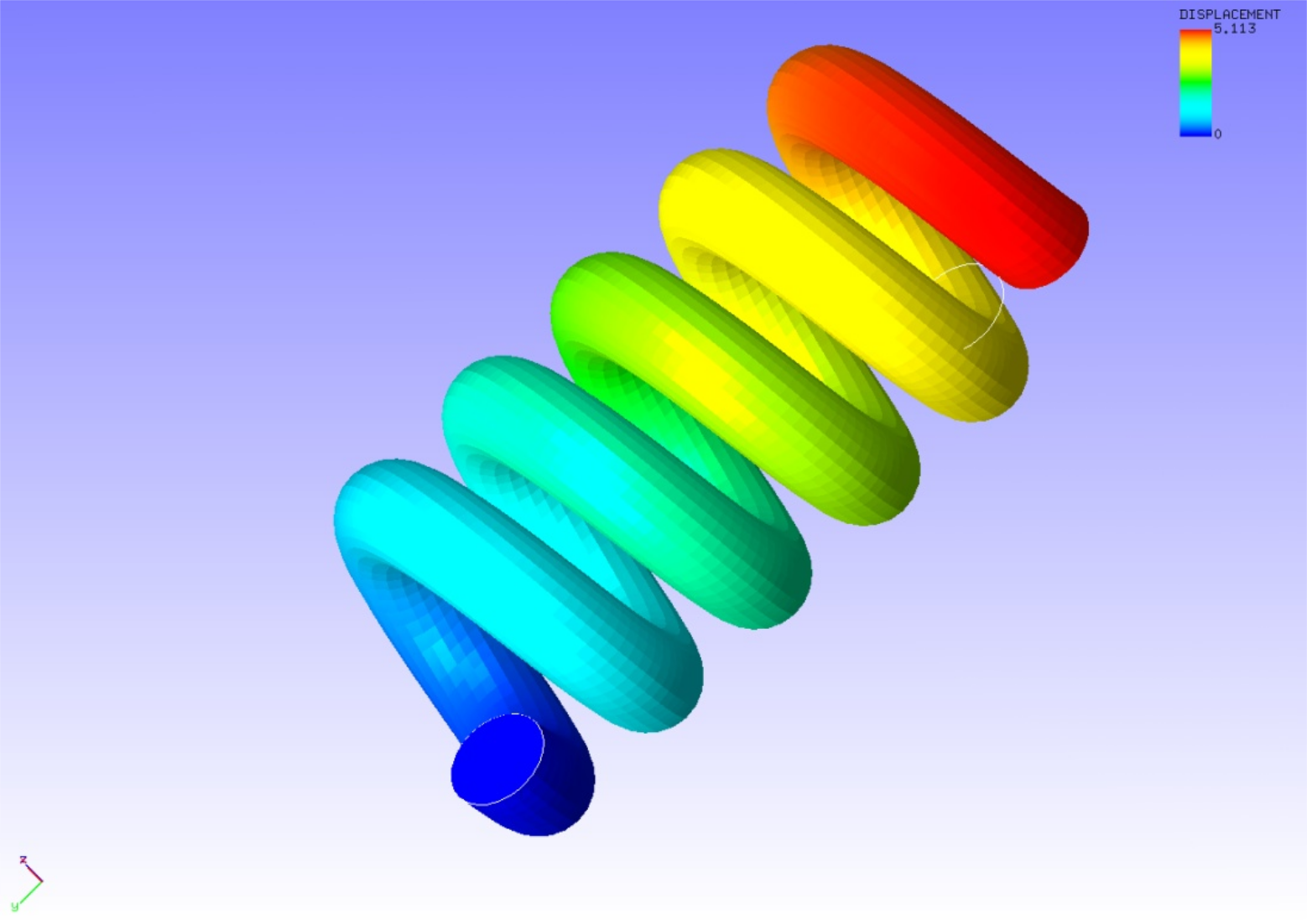
Fig. 4.4.3: Analysis results of deformation and displacement
Log file 0.log
 fstr_setup: OK
#### Result step=     0
 ##### Local Summary @Node    :Max/IdMax/Min/IdMin####
 //U1    0.0000E+00         1  0.0000E+00         1
 //U2    0.0000E+00         1  0.0000E+00         1
 //U3    0.0000E+00         1  0.0000E+00         1
 //E11   0.0000E+00         1  0.0000E+00         1
 //E22   0.0000E+00         1  0.0000E+00         1
 //E33   0.0000E+00         1  0.0000E+00         1
 //E12   0.0000E+00         1  0.0000E+00         1
 //E23   0.0000E+00         1  0.0000E+00         1
 //E31   0.0000E+00         1  0.0000E+00         1
 //S11   0.0000E+00         1  0.0000E+00         1
 //S22   0.0000E+00         1  0.0000E+00         1
 //S33   0.0000E+00         1  0.0000E+00         1
 //S12   0.0000E+00         1  0.0000E+00         1
 //S23   0.0000E+00         1  0.0000E+00         1
 //S31   0.0000E+00         1  0.0000E+00         1
 //SMS   0.0000E+00         1  0.0000E+00         1
 ##### Local Summary @Element :Max/IdMax/Min/IdMin####
 //E11   0.0000E+00         1  0.0000E+00         1
 //E22   0.0000E+00         1  0.0000E+00         1
 //E33   0.0000E+00         1  0.0000E+00         1
 //E12   0.0000E+00         1  0.0000E+00         1
 //E23   0.0000E+00         1  0.0000E+00         1
 //E31   0.0000E+00         1  0.0000E+00         1
 //S11   0.0000E+00         1  0.0000E+00         1
 //S22   0.0000E+00         1  0.0000E+00         1
 //S33   0.0000E+00         1  0.0000E+00         1
 //S12   0.0000E+00         1  0.0000E+00         1
 //S23   0.0000E+00         1  0.0000E+00         1
 //S31   0.0000E+00         1  0.0000E+00         1
 //SMS   0.0000E+00         1  0.0000E+00         1
 ##### Global Summary @Node    :Max/IdMax/Min/IdMin####
 //U1    0.0000E+00         1  0.0000E+00         1
 //U2    0.0000E+00         1  0.0000E+00         1
 //U3    0.0000E+00         1  0.0000E+00         1
 //E11   0.0000E+00         1  0.0000E+00         1
 //E22   0.0000E+00         1  0.0000E+00         1
 //E33   0.0000E+00         1  0.0000E+00         1
 //E12   0.0000E+00         1  0.0000E+00         1
 //E23   0.0000E+00         1  0.0000E+00         1
 //E31   0.0000E+00         1  0.0000E+00         1
 //S11   0.0000E+00         1  0.0000E+00         1
 //S22   0.0000E+00         1  0.0000E+00         1
 //S33   0.0000E+00         1  0.0000E+00         1
 //S12   0.0000E+00         1  0.0000E+00         1
 //S23   0.0000E+00         1  0.0000E+00         1
 //S31   0.0000E+00         1  0.0000E+00         1
 //SMS   0.0000E+00         1  0.0000E+00         1
 ##### Global Summary @Element :Max/IdMax/Min/IdMin####
 //E11   0.0000E+00         1  0.0000E+00         1
 //E22   0.0000E+00         1  0.0000E+00         1
 //E33   0.0000E+00         1  0.0000E+00         1
 //E12   0.0000E+00         1  0.0000E+00         1
 //E23   0.0000E+00         1  0.0000E+00         1
 //E31   0.0000E+00         1  0.0000E+00         1
 //S11   0.0000E+00         1  0.0000E+00         1
 //S22   0.0000E+00         1  0.0000E+00         1
 //S33   0.0000E+00         1  0.0000E+00         1
 //S12   0.0000E+00         1  0.0000E+00         1
 //S23   0.0000E+00         1  0.0000E+00         1
 //S31   0.0000E+00         1  0.0000E+00         1
 //SMS   0.0000E+00         1  0.0000E+00         1
#### Result step=     1
 ##### Local Summary @Node    :Max/IdMax/Min/IdMin####
 //U1    2.6070E-01     42179 -2.4651E-01     44163
 //U2    2.0567E-02     14512 -5.0036E+00     44753
 //U3    6.6559E-02     15443 -6.6862E-01     44664
 //E11   4.1026E-03      1015 -4.5809E-03      3429
 //E22   2.3030E-03     42626 -1.5152E-03     44761
 //E33   4.1949E-03     23553 -5.0169E-03     27938
 //E12   1.3348E-02     55149 -1.3381E-02     56829
 //E23   2.7881E-02     48353 -1.9534E-02     48322
 //E31   1.0861E-02     47938 -8.8803E-03      9493
 //S11   8.4247E-03      8264 -9.1017E-03      8501
 //S22   1.0769E-02     56772 -6.3921E-03     56787
 //S33   1.3881E-02     56764 -1.2778E-02     42632
 //S12   1.2396E-02     55149 -1.2434E-02     56829
 //S23   2.5880E-02     48353 -1.8138E-02     48322
 //S31   1.0081E-02     47938 -8.2435E-03      9493
 //SMS   4.9638E-02     48353  2.8482E-04     66578
 ##### Local Summary @Element :Max/IdMax/Min/IdMin####
 //E11   3.9156E-03     34074 -4.3403E-03     16932
 //E22   1.8391E-03     23282 -1.2721E-03     56220
 //E33   3.9490E-03     45925 -4.4530E-03     34145
 //E12   1.2578E-02     45680 -1.1729E-02     19492
 //E23   2.0534E-02     40739 -1.3512E-02     24172
 //E31   9.4162E-03     32786 -7.6149E-03     44971
 //S11   7.7882E-03     25880 -8.2932E-03     45925
 //S22   6.8884E-03     23275 -6.1373E-03     49821
 //S33   9.9242E-03     59974 -9.5475E-03     31626
 //S12   1.1679E-02     45680 -1.0893E-02     19492
 //S23   1.9071E-02     40739 -1.2534E-02     24172
 //S31   8.7376E-03     32786 -7.0660E-03     44971
 //SMS   3.5586E-02     40739  4.1161E-04     40537
 ##### Global Summary @Node    :Max/IdMax/Min/IdMin####
 //U1    2.6070E-01     42179 -2.4651E-01     44163
 //U2    2.0567E-02     14512 -5.0036E+00     44753
 //U3    6.6559E-02     15443 -6.6862E-01     44664
 //E11   4.1026E-03      1015 -4.5809E-03      3429
 //E22   2.3030E-03     42626 -1.5152E-03     44761
 //E33   4.1949E-03     23553 -5.0169E-03     27938
 //E12   1.3348E-02     55149 -1.3381E-02     56829
 //E23   2.7881E-02     48353 -1.9534E-02     48322
 //E31   1.0861E-02     47938 -8.8803E-03      9493
 //S11   8.4247E-03      8264 -9.1017E-03      8501
 //S22   1.0769E-02     56772 -6.3921E-03     56787
 //S33   1.3881E-02     56764 -1.2778E-02     42632
 //S12   1.2396E-02     55149 -1.2434E-02     56829
 //S23   2.5880E-02     48353 -1.8138E-02     48322
 //S31   1.0081E-02     47938 -8.2435E-03      9493
 //SMS   4.9638E-02     48353  2.8482E-04     66578
 ##### Global Summary @Element :Max/IdMax/Min/IdMin####
 //E11   3.9156E-03     34074 -4.3403E-03     16932
 //E22   1.8391E-03     23282 -1.2721E-03     56220
 //E33   3.9490E-03     45925 -4.4530E-03     34145
 //E12   1.2578E-02     45680 -1.1729E-02     19492
 //E23   2.0534E-02     40739 -1.3512E-02     24172
 //E31   9.4162E-03     32786 -7.6149E-03     44971
 //S11   7.7882E-03     25880 -8.2932E-03     45925
 //S22   6.8884E-03     23275 -6.1373E-03     49821
 //S33   9.9242E-03     59974 -9.5475E-03     31626
 //S12   1.1679E-02     45680 -1.0893E-02     19492
 //S23   1.9071E-02     40739 -1.2534E-02     24172
 //S31   8.7376E-03     32786 -7.0660E-03     44971
 //SMS   3.5586E-02     40739  4.1161E-04     40537